free counters 

Standish Hall

Standish Hall, an experiment in Radar Control

Standish Hall is an experimental project of a battery electric diesel outline locomotive with forward facing RADAR.

Built on an IP engineering Delux chassis with an  Arduino Nano providing RADAR and motor control in automatic mode, the  loco also has full radio control for speed and forward / reverse.

The track is scanned up to 300mm ahead for stationary or slow moving objects and the controller will either adjusts the loco's speed accordingly or bring the loco to a complete stop.

Automatic mode can be selected from the R/C transmitter with automatic mode being the default if the transmitter is switched off.

sh3

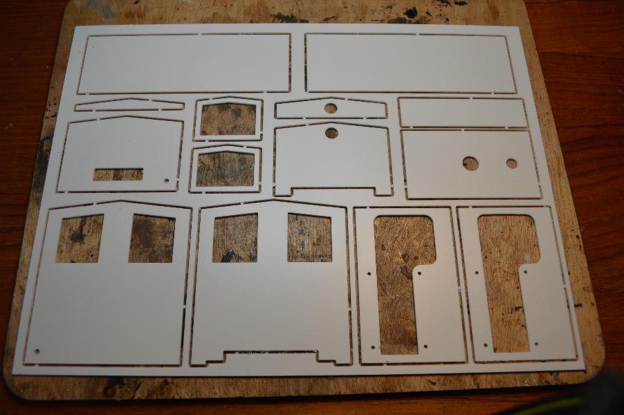
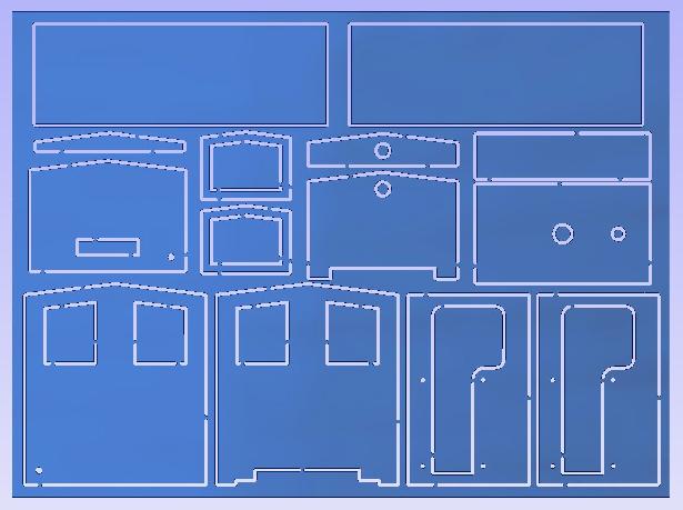
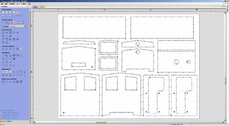
2D CAD design for the bodywork and dashboard using CorelDRAW and VcarvePRO.

sh2
sh1

Although the CAD is 2D you have to think in 3D to get the final design correct.

sh5

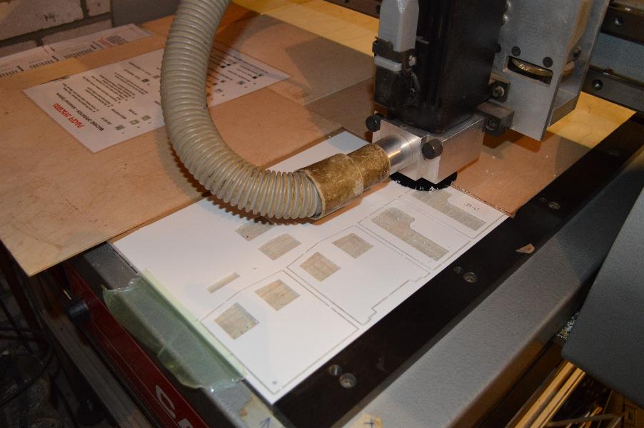
Bodywork being cut out on a Pacer CNC router.

sh6
RL1

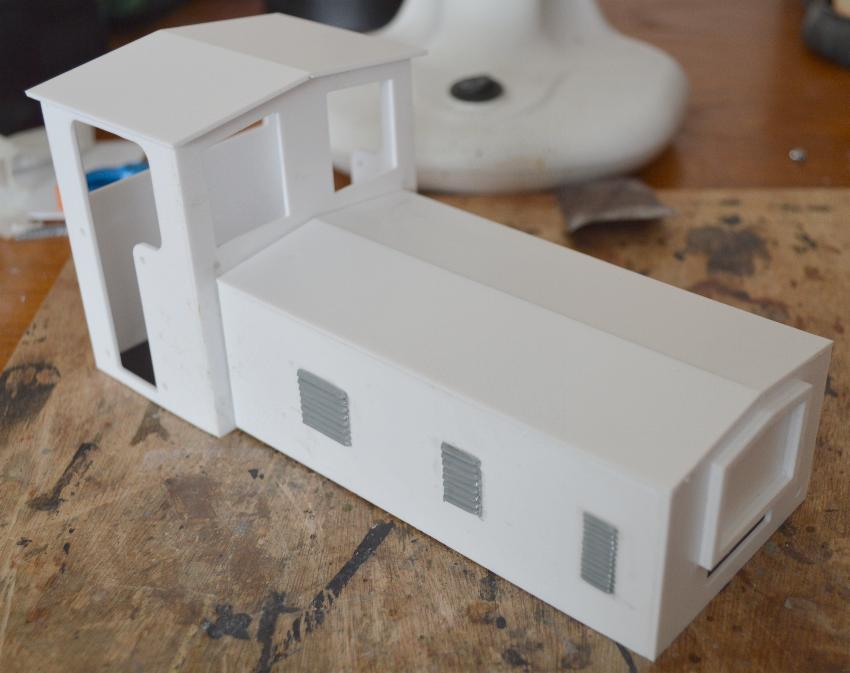
The assembled bodywork

sh4

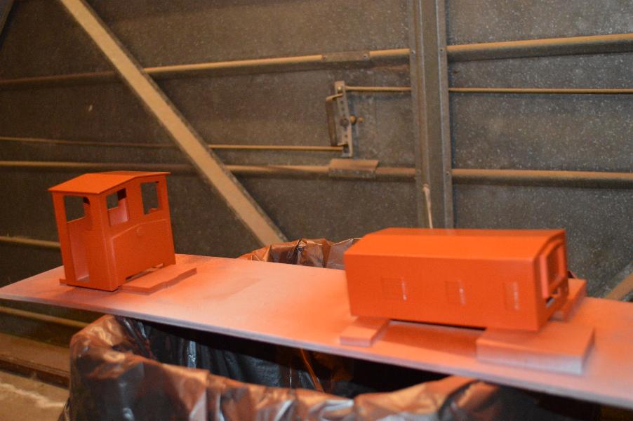
Into the paint shop for the primer coat.

DSC_0253

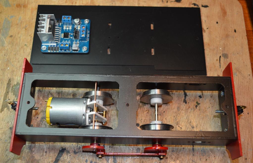
IP Engineering Delux chassis modified to take 20:1 ratio metal gears along with the base plate with the H bridge motor driver already in place.

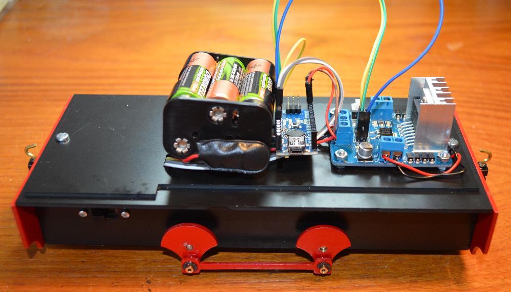
A temporary lash up of the electronics, an Arduino Nano provides the motor control through an H bridge motor driver, RADAR control and interface to the radio control receiver.

DSC_0255
DSC_0264

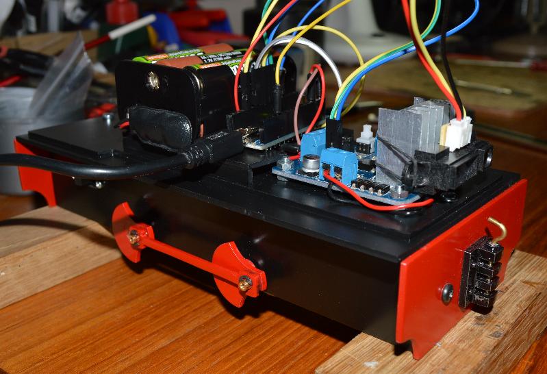
A more permanent solution for the electronics showing the Radar under test and USB connection to the MAC.

The front buffer hasn’t yet been changed for the one with the emergency stop switch in it.

Screen Shot 2013-06-04 at 15.31.54

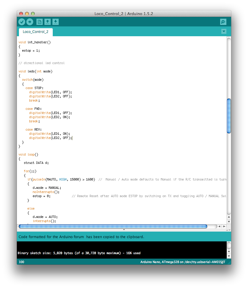
The control software is written in C++ using the Arduino compiler on a MAC.

In manual mode it reads the 3 channels from the radio control for speed, direction and mode and drives the PWM for motor speed and direction control as well as switching the directional lights.

In automatic mode, which can be selected by channel 5 on the radio control (default when the R/C transmitter is switched off), the software reads the distance information from the RADAR module, processes it and adjusts the motor controller PWM to slow the loco or bring it to a complete stop depending on the distance to the detected object.

There is also an emergency fail-safe triggered by a button on the front buffer which will bring the loco to an immediate stop if the RADAR fails to detect something.

After an emergency stop the loco will flash its directional lights and will then have to be reset either manually by pressing the red button in the cab or remotely by toggling the mode switch on the radio control transmitter.

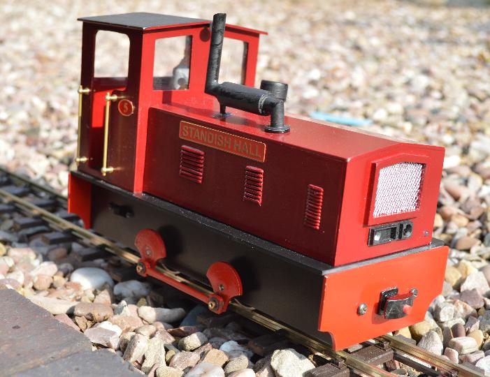
The finished loco on the WVLR test track showing the RADAR unit neatly located under the radiator grill.

The red button in the front buffer is an emergency stop incase the RADAR fails to see an object on the track ahead.

DSC_0334
[Home] [Projects] [Data Wagon] [Standish Hall] [Anti-Gravity Train] [Criccieth Castle]